

An oversized pump isn't a safety margin; it's a direct tax on your facility's bottom line and equipment lifespan. You likely prioritize system uptime above all else, yet many industrial sites suffer from chronic energy waste and mechanical seal failures simply because the hardware doesn't match the hydraulic reality. Mastering the interaction of the system curve vs pump curve is the only way to eliminate these inefficiencies. This guide provides the technical framework to optimize flow and ensure long-term reliability for your Goulds Water Technology Pumps.
We'll examine how to calculate Total Dynamic Head accurately, diagnose operating points far from the Best Efficiency Point, and apply current ANSI/HI 9.8-2024 standards to your intake designs. You'll also learn the specific impact of impeller trimming and how to solve Net Positive Suction Head (NPSH) issues in challenging environments like remote mining sites. By the end of this guide, you'll have the diagnostic tools needed to transform pump performance from a source of maintenance headaches into a streamlined asset that meets rigorous U.S. Department of Energy efficiency regulations.
Key Takeaways
- Identify the precise intersection of the system curve vs pump curve to determine the actual operating point and eliminate energy waste from oversized equipment.
- Locate the Best Efficiency Point (BEP) on the pump performance curve to maximize mechanical seal life and reduce the risk of shaft deflection.
- Evaluate the technical advantages of impeller trimming and VFD speed adjustments to align pump output with specific system requirements without using inefficient throttling valves.
- Select the correct frame size and metallurgy for Goulds Water Technology Pumps to ensure durable performance in corrosive or abrasive industrial environments.
What is a Pump Performance Curve? Understanding the Axes
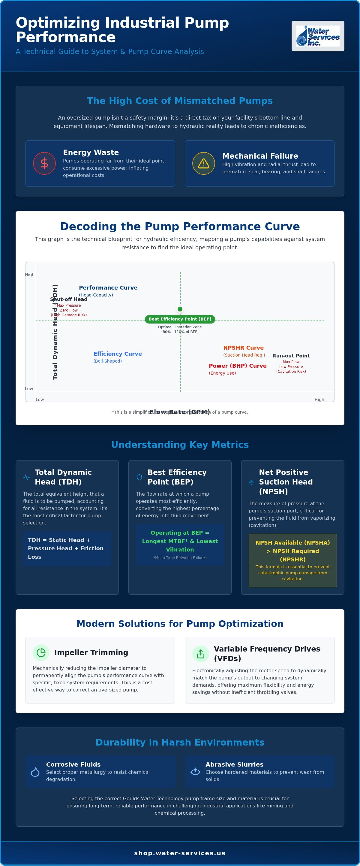
A Pump Performance Curve serves as the technical blueprint for any hydraulic installation. It's a graphical representation of a pump's capacity to move fluid against specific resistance. To optimize an industrial site, engineers must evaluate the system curve vs pump curve to find the ideal operating point. The Y-axis on this chart displays Total Dynamic Head (TDH), measured in feet or meters. This represents the total energy imparted to the fluid. The X-axis tracks the Flow Rate, usually measured in Gallons Per Minute (GPM) or cubic meters per hour (m³/h).
Industrial standards prioritize Head over PSI. This is because Head remains independent of fluid density. A pump will move a liquid to a specific height regardless of its specific gravity. For example, Goulds Water Technology Pumps provide consistent head performance whether the medium is clean water or high-density slurry. Using Head ensures that engineering calculations remain accurate across varying temperatures and chemical compositions. It allows for a universal comparison between different pump models without adjusting for fluid weight.
Total Dynamic Head (TDH) vs. Static Head
Calculating TDH is a critical requirement for accurate pump selection. Static head is simply the vertical lift from the source to the discharge point. However, TDH accounts for the total resistance the pump must overcome. It includes static head, pressure head, and friction loss. Engineers utilize the Hazen-Williams equation to determine friction loss in complex piping networks found in mining or chemical processing. This calculation considers pipe length, diameter, and the "C" factor for internal roughness. Precise TDH data prevents the common error of installing oversized pumps that waste energy and increase operational costs.
The Relationship Between Flow and Pressure
Centrifugal pumps operate with a clear inverse relationship between pressure and volume. As system resistance increases, the flow rate naturally drops. The curve starts at the Shut-off Head. This represents the maximum pressure a pump can generate when the discharge valve is fully closed. Running at this point causes mechanical damage due to heat. Conversely, the Run-out Point is the maximum flow at the lowest possible head. Operating near the run-out point often causes motor overload and cavitation. Reliability depends on staying within the preferred operating range between these two extremes to maintain mechanical integrity.
The Four Essential Lines on an Industrial Pump Curve
An industrial pump datasheet integrates four distinct data sets into a single graphical display. Understanding how these lines interact is the only way to accurately evaluate the system curve vs pump curve for long term reliability. A professional grade curve for Goulds Water Technology Pumps typically includes the following:
- The Performance (Head-Capacity) Curve: This primary arc defines the pump's hydraulic capability, showing exactly how much head the unit generates at any given flow rate.
- The Efficiency Curve: A bell-shaped line that identifies the percentage of energy successfully transferred to the fluid, peaking at the Best Efficiency Point (BEP).
- The Power (Brake Horsepower) Curve: This mapping of energy consumption (BHP or kW) across the flow range is vital for sizing motors and preventing electrical overloads.
- The Net Positive Suction Head Required (NPSHR) Curve: A critical specification that dictates the minimum pressure required at the suction inlet to prevent fluid from vaporizing.
Finding the Best Efficiency Point (BEP)
Operating a pump at its BEP ensures the lowest possible vibration and the longest mean time between failures (MTBF). Engineers should aim to maintain operation within 80% to 110% of this point. When a system forces a pump to operate too far left of the curve, the low flow leads to excessive heat buildup and premature bearing failure. Conversely, operating too far to the right causes high radial thrust, shaft deflection, and motor overload. Maintaining hydraulic stability requires a precise match between the pump's peak efficiency and the actual system requirements.
NPSHR vs. NPSHA: Preventing Pump Damage
Cavitation is the most common cause of catastrophic pump failure in remote industrial sites. NPSHR is a fixed manufacturer specification that increases as flow increases. NPSH Available (NPSHA), however, is a site-specific calculation. In high-altitude mining environments or hot process water applications, atmospheric pressure is lower and vapor pressure is higher. These factors significantly reduce NPSHA. If the NPSHA does not exceed the NPSHR by at least 2 to 5 feet, vapor bubbles will form and collapse against the impeller, causing pitting and hardware destruction. Always verify your site's atmospheric pressure and fluid temperature before finalizing a pump selection to ensure the suction head margin is sufficient for continuous operation.
Variables That Modify Pump Curve Data
Static pump curves provide a baseline, but actual industrial performance fluctuates based on mechanical and fluid variables. Understanding the system curve vs pump curve requires accounting for how modifications like impeller trimming and speed adjustments alter hydraulic output. These variables allow engineers to tune hardware to the specific needs of a facility rather than relying on generic factory settings.
Impeller Diameter and System Matching
Manufacturers like Goulds Water Technology Pumps often provide charts with multiple arcs representing different impeller trims. Trimming a pump's impeller is a permanent mechanical modification used to match a specific duty point precisely. This method is significantly more energy efficient than using a discharge valve to restrict flow, as it reduces the energy imparted to the fluid at the source. A 10% reduction in impeller diameter results in a roughly 10% reduction in flow. It's a precise solution for systems where the pump is consistently oversized for the required Total Dynamic Head.
Affinity Laws for Industrial Maintenance
The Affinity Laws serve as the mathematical foundation for predicting pump behavior when speed or diameter changes. The most critical of these is the Cubic Rule. Doubling the pump speed requires eight times the brake horsepower. This exponential relationship highlights the importance of precise speed management for energy ROI. Small reductions in speed lead to massive savings in operational costs, making speed control one of the most effective ways to optimize industrial utility consumption.
Variable Frequency Drives (VFDs) allow operators to shift the entire performance curve vertically to meet varying demand. This is essential in commercial reverse osmosis water filtration systems, where membrane fouling increases resistance over time. Integrating Walchem controllers enables automated speed adjustments based on real-time sensor data, ensuring the pump stays near its Best Efficiency Point regardless of fluctuating system conditions.
Fluid properties also dictate curve behavior. High viscosity fluids, such as thick mining slurries, create internal friction that flattens the performance curve. This reduces both the head and flow capacity compared to water. Specific gravity affects power consumption linearly; a fluid twice as heavy as water will require twice the horsepower to move at the same flow and head. Engineers must apply correction factors from the Hydraulic Institute when dealing with non-aqueous fluids to ensure the motor and pump are sized for the actual load.
Matching the Pump Curve to the System Curve
The system curve represents the hydraulic resistance of the entire piping network. It's a parabolic line that starts at the static head and rises as flow increases. The precise point where the pump curve meets the system curve is the operating point. This intersection is the only place the system will actually function. Understanding the system curve vs pump curve relationship is vital because the system curve is not a fixed entity. In industrial water filtration systems, the curve shifts over time. As sediment builds up on media or membranes, resistance increases. This forces the operating point to move to the left, resulting in higher pressure and lower flow capacity.
Calculating System Resistance
Accurate resistance calculations must include every component in the flow path. This involves totaling the friction losses from pipe runs, valves, elbows, and water flow meter GPM sensors. Small diameter pipes significantly increase friction head, which raises the power requirements of the motor. Theoretical models often deviate from reality due to internal pipe scaling or installation variances. Use Ashcroft pressure gauges at the suction and discharge ports to verify the actual system curve. Comparing these real-world readings to the manufacturer's performance data helps diagnose hidden blockages or pump wear.
Pumps in Parallel and Series
Multi-pump configurations allow for greater operational flexibility. In parallel pumping, two or more pumps discharge into a common header. This increases total flow capacity while maintaining the same head. It's a standard approach for high-volume mining water applications where demand fluctuates. Conversely, series pumping involves the discharge of one pump feeding the suction of the next. This doubles the head capacity, which is necessary for high-lift applications or deep mine dewatering. Both methods require careful planning to ensure the pumps operate near their Best Efficiency Point.
Improperly configured multi-pump systems lead to hydraulic instability. If pumps with different curves are placed in parallel, the stronger pump can "deadhead" the weaker one. This forces the weaker pump to operate at zero flow, causing rapid heat buildup and mechanical failure. Always ensure the pumps are matched and the system curve allows for stable operation across the entire flow range. To ensure your hardware matches your hydraulic requirements, browse our full inventory of Goulds Water Technology Pumps for reliable industrial performance.
Selecting Goulds Water Technology Pumps for Industrial Systems
Goulds Water Technology Pumps represent the industry standard for high-stakes applications, particularly in mining wastewater treatment. These environments demand hardware that can withstand extreme pH levels and abrasive solids without frequent downtime. Proper selection requires more than just matching a flow rate. Engineers must choose the correct frame size and metallurgy, such as 316 stainless steel or duplex alloys, to ensure chemical compatibility. Failure to align the material properties with the fluid's corrosive profile leads to rapid impeller degradation and a total shift in hydraulic output. This makes the initial technical evaluation of the system curve vs pump curve even more critical for long-term operational stability.
Water Services, Inc. specializes in the integration of these pumps into modular and containerized treatment plants. These systems often serve military operations or remote industrial sites where reliability is the primary metric of success. By utilizing robust Goulds hardware, we ensure that the pumping system remains stable even under fluctuating suction conditions. Our engineering team provides the technical oversight necessary to verify that every component, from the mechanical seal to the motor frame, is specified for the rigors of the field. This specialized approach reduces the risk of unexpected downtime in environments where logistical support is limited.
Duty Point Specification for RO Systems
High-pressure membrane systems require precise hydraulic control to maintain efficiency. Matching a pump to a commercial reverse osmosis system involves meeting the strict pressure requirements of FilmTec and Hydranautics membranes. The pump must provide consistent flux even as the feed water temperature or salinity varies. If the pump cannot maintain the required pressure, the recovery rate drops and membrane scaling increases. This leads to premature system failure and expensive replacement costs. We analyze the system curve vs pump curve to ensure the operating point stays within the design limits of the RO membranes throughout their entire service life.
Procurement and Technical Support
Navigating the Water Services pump collection allows industrial buyers to source standardized parts with documented performance metrics. We provide more than just hardware; we offer the engineering consulting needed for complex containerized treatment plants in remote locations. Whether you're managing a remote mine or a municipal water facility, our team can assist with custom system engineering and hydraulic modeling. Professional curve analysis is the next step in optimizing your site. Contact Water Services, Inc. today to request a comprehensive review of your specific industrial system and ensure your pumping infrastructure is engineered for maximum reliability.
Optimizing Industrial Hydraulic Performance
Achieving peak operational efficiency requires a precise alignment between your hardware and your piping network. By mastering the relationship of the system curve vs pump curve, you eliminate the mechanical stressors that lead to premature seal failure and motor overload. You've learned how dynamic resistance from filter fouling and site-specific NPSH requirements dictate the true operating point. Maintaining this balance isn't just about energy savings; it's about protecting your infrastructure from catastrophic failure.
Water Services, Inc. serves as your technical partner in these complex environments. As an Authorized Goulds Water Technology Distributor, we provide the specialized engineering support needed for modular water systems and remote mining operations. Our global logistical reach ensures that high-performance components arrive at your site ready for deployment. We focus on technical integrity so you don't have to worry about mismatched hardware. Shop Goulds Water Technology Pumps and Industrial Components to secure the reliability your facility demands. Proper hydraulic selection is a permanent investment in your site's long-term uptime.
Frequently Asked Questions
What is the difference between a flat and steep pump curve?
A steep pump curve shows a significant change in head for a small change in flow rate, providing greater stability in systems with fluctuating resistance. A flat curve maintains a relatively constant head across a wide range of flow volumes. Engineers typically select steep curves when maintaining a specific flow is critical. Understanding the system curve vs pump curve intersection helps determine which profile provides the most hydraulic stability for your piping network.
How does viscosity affect a centrifugal pump's performance curve?
Increased fluid viscosity creates additional internal friction within the pump casing and impeller vanes. This results in a flattened performance curve characterized by reduced flow capacity and lower total dynamic head compared to water-based testing. Power consumption also increases as the motor works harder to shear the thicker fluid. Engineers must apply Hydraulic Institute correction factors when selecting Goulds Water Technology Pumps for heavy mining slurries or viscous chemical processing applications.
What happens if I operate my pump at the shut-off point?
Operating at the shut-off point means the pump is running against a closed discharge valve with zero flow. At this point, the motor's energy is converted entirely into heat and vibration rather than fluid movement. This leads to rapid temperature spikes that vaporize the liquid, causing mechanical seal failure and warped internal components. You shouldn't run a centrifugal pump at shut-off for more than a few seconds without a bypass or minimum flow line.
Can I use a pump curve to troubleshoot low flow issues in my RO system?
You can diagnose RO flow issues by plotting your actual flow and pressure readings against the original manufacturer's curve. If the measured operating point falls below the curve, it indicates internal pump wear or a damaged impeller. If the point stays on the curve but moves left, the problem is likely increased system resistance from fouled membranes. This technique effectively separates pump performance issues from broader system curve vs pump curve resistance changes.
How do I calculate Total Dynamic Head for my industrial site?
Total Dynamic Head (TDH) is the sum of three primary components: static head, friction head, and operating pressure head. Static head measures the vertical lift from the source to the destination. Friction head accounts for resistance in pipes, valves, and fittings, often calculated using the Hazen-Williams equation. Finally, add the required discharge pressure at the end of the line. Accurate TDH calculation is essential to ensure your pump operates at its intended duty point.
What is the Best Efficiency Point (BEP) and why is it critical?
The Best Efficiency Point (BEP) is the specific flow rate where the pump operates with the highest hydraulic efficiency. At this point, the radial forces on the impeller are balanced, which minimizes shaft deflection and vibration. Operating near the BEP significantly extends the life of mechanical seals and bearings. Most industrial standards recommend maintaining operation within 80% to 110% of the BEP to ensure equipment reliability and reduce long-term energy costs.
How does altitude affect the Net Positive Suction Head (NPSH) requirements?
High altitude reduces the atmospheric pressure acting on the surface of the suction liquid. This directly decreases the Net Positive Suction Head Available (NPSHA) to the pump. In remote mining sites located at high elevations, this reduction can lead to cavitation even if the pump meets standard sea-level specifications. Engineers must adjust their site-specific calculations to ensure NPSHA remains at least 2 to 5 feet above the manufacturer's NPSH Required (NPSHR) to prevent damage.
Why should I avoid operating a pump at the run-out point?
The run-out point is the maximum flow capacity at the far right of the performance curve where head is at its minimum. Operating here causes extreme turbulence and high fluid velocity, which often leads to severe cavitation and motor overload. The lack of backpressure allows the pump to draw excessive horsepower, potentially tripping circuit breakers or burning out the motor windings. Staying within the manufacturer's recommended operating range prevents these catastrophic mechanical failures.
0 comentarios