

Lead-lag and standby control serve different purposes: lead-lag assigns operating priority and may rotate which pump leads, while standby control keeps a pump ready to respond when the duty pump cannot meet the control requirement. In an industrial standby pump configuration, define which eligible, stopped pump is selected and what condition triggers backup operation. That distinction determines how a two-pump system starts, changes over, and signals a fault.
A second installed pump does not automatically provide reliable backup. Readiness depends on the pump, controls, power supply, and hydraulic path all being available. This guide explains how lead-lag differs from standby operation, which pumps qualify for automatic selection, and how to choose a practical two-pump arrangement. It also covers changeover logic, runtime-based selection, and checks that show whether the standby pump is ready when called.
Key Takeaways
- Separate lead-lag rotation from standby changeover so each pump’s role and backup trigger are clear.
- Define automatic eligibility around operating status and control readiness, not pump availability alone.
- Match the arrangement to process demand, required capacity, and the way the system should respond to a pump fault.
- Use confirmed running feedback and controlled changeover tests to assess whether the backup sequence works as intended.
Automatic mode and pump eligibility
Automatic operation depends on control inputs, settings, and hydraulic paths that allow changeover. A failed pressure transducer can hide a demand signal; an outdated controller setting can block transfer. A tripped disconnect or closed valve can also prevent the selected standby pump from starting or delivering flow. Treat each condition as an eligibility fault, not merely a pump-selection issue.
Define eligibility before assigning duty or standby status. Consider a pump available only when its control mode, electrical supply, required valves, and operating feedback meet the sequence conditions. For example, a pump isolated for maintenance should not be selected automatically. In a three-duty, two-standby arrangement, the controller needs a clear rule for choosing an available standby when demand exceeds the active pumps’ capacity.
Document how the controller resolves ties. It can use a fixed secondary order or retain the rotation order when eligible pumps have equal priority. Re-evaluate selection at defined events, such as new demand, loss of a duty pump, return to automatic operation, or a site-defined rotation event. This avoids ambiguity when several pumps appear equally suitable.
Test mode should remain distinct from normal automatic operation. One example assigns I:0/8 to the Test_Mode selector and I:0/9 to Test_Enable. Runtime tracking should use confirmed running feedback, not the start command alone. If both the command and feedback are off, the accumulator must not increase. Preserve the remainder below one hour so partial operating time isn’t discarded. Runtime values should also remain valid after a controller restart or HMI download. Read a cascade delay from the existing project or HMI setting rather than assigning an arbitrary value.
Include eligibility checks in commissioning and routine maintenance. Inspect seals, check valves, couplings, and electrical connections: extended inactivity can contribute to dry seals, corrosion, or stuck valves. Record each standby test result and assign corrective work promptly. After testing, remove and document temporary bypasses or control overrides so the automatic sequence returns to its intended operating state.
Configuration selection factors
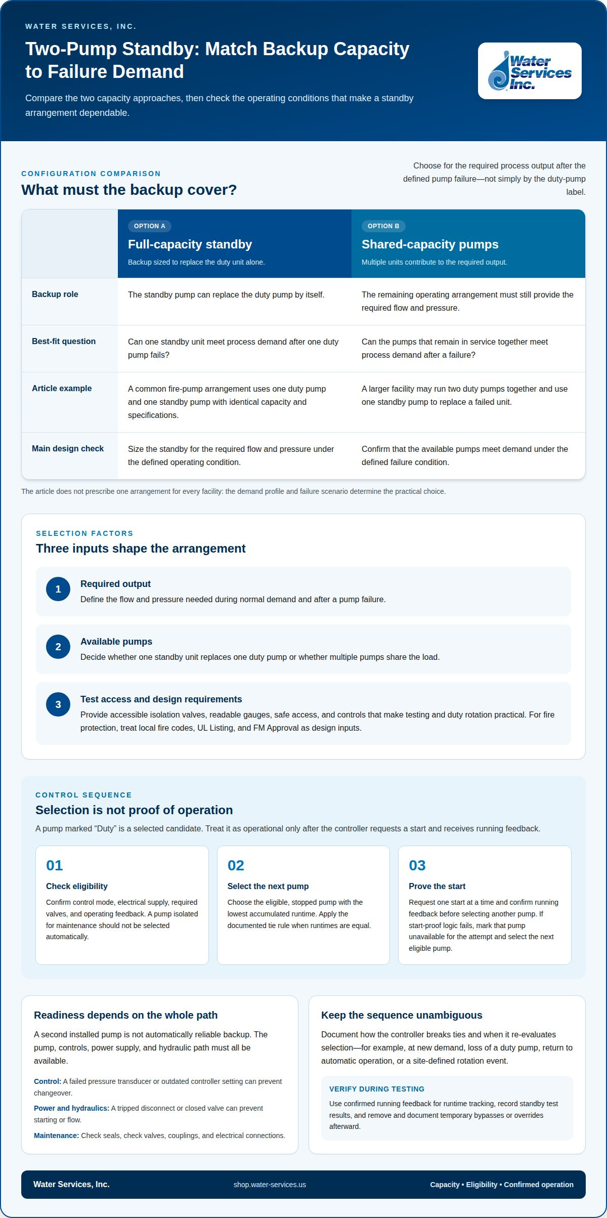
An industrial standby pump doesn't always need 100% capacity. Choose full or shared capacity based on required process demand after a pump failure. A full-capacity standby can replace the duty unit alone. Shared-capacity pumps may suit systems where multiple units together meet demand, provided the remaining operating arrangement supplies the required flow and pressure.
Start with the failure scenario: will the standby replace one failed pump or support several pumps operating together? A common fire-pump arrangement uses one duty pump and one standby pump with identical capacity and specifications. Larger facilities may operate two duty pumps together and use one standby pump to replace a failed unit. The right arrangement depends on the demand profile.
Power supply and access also affect the arrangement. For a standby fire pump, a different power source from the duty pump is recommended. The pump-room layout should provide clear isolation valves, readable gauges, safe access, and controls that make duty rotation straightforward. These details determine whether operators can test the backup without an awkward manual sequence or shutdown.
- Required output: Define the flow and pressure needed during normal demand and after a failure.
- Available pumps: Decide whether one standby unit replaces one duty pump or shares the load.
- Test access: Make valves, gauges, and controls accessible for routine standby checks.
Local fire codes, UL Listing, and FM Approval may specify duty-and-standby arrangements. Treat those requirements as design inputs for fire-protection applications. For other industrial processes, base the arrangement on required operating capacity and the consequences of losing a pump. A configuration is suitable when available pumps can meet demand under the defined failure condition and the rotation and test procedures are practical.
Duty selection versus motor starting
Size the standby pump for the required process flow and pressure under the defined operating condition. Account for system demand, hydraulic resistance, and the duty the backup must perform after a failure. Select capacity to meet that requirement, rather than relying on the duty pump’s label.
Pump selection and starting are separate control decisions. A pump marked “Duty” is the selected candidate, not proof that its motor has started. The controller must issue a start request and receive running feedback before treating the pump as operational. This distinction matters in a four-pump system, where several units may be eligible but process demand determines how many should run.
Before filling a duty position, evaluate each pump’s eligibility. Select the eligible stopped pump with the lowest accumulated runtime, applying the documented tie rule if runtimes are equal. The controller should request one start at a time and confirm running feedback before selecting another pump. This prevents multiple start commands when the process needs only one additional unit.
- Demand: Determine the flow and pressure needed for the current operating condition.
- Selection: Choose an eligible stopped pump according to runtime and the tie rule.
- Proof: Confirm running feedback before filling another duty position.
Starting pumps simply because multiple duty positions exist can waste energy or exceed process needs. Replacing a running pump whenever another has slightly lower accumulated runtime can also cause unnecessary starts. Keep the running unit in service unless the control sequence defines a reason to change it.
If a selected motor receives a start command but fails its start-proof logic, mark it unavailable for that attempt and select the next eligible pump. Manual operation should not silently bypass this status. A clear alarm and selection record help operators distinguish a failed start from a pump that was never selected. Duty assignment identifies the intended pump; feedback confirms whether its motor runs.
Two-pump standby system operation
A two-pump system depends on piping, power, controls, and testing that support changeover. Define the failure response so operators can verify that the standby pump starts and delivers the required pressure or flow.
Suction and Discharge Piping
Duty and standby pumps commonly connect to shared suction and discharge headers, with isolation and check valves controlling each pump’s path. This lets the standby take over without the failed unit obstructing the flow path. Confirm valve positions and check-valve operation during readiness checks. Where the design uses one, a small bypass with a manual valve across the non-return valve can serve as a warm-up line.
Automatic Standby Start Controls
Automatic standby control starts the backup when the duty pump fails to restore pressure within the configured time. The sequence should confirm the duty pump’s running feedback, identify a failure, then command the standby and verify its response. The example transfer test calls for Pump 2 to start within 500 milliseconds or the configured time-delay setting. Backup power depends on the drive and application; diesel-driven fire pumps require fuel storage for at least 8 hours of continuous operation.
In the United States, NFPA 20 covers stationary pumps for fire protection, while NFPA 25 covers inspection, testing, and maintenance of water-based fire protection systems. UL Listing, FM Approval, and local fire codes may also shape fire-pump arrangements.
Testing, Maintenance, and Failure Risks
Standby testing simulates a failure under controlled conditions, then verifies startup, required pressure or flow, and alarm delivery. For fire pumps, the outlined routine includes weekly start tests, monthly controller, battery, valve, and power-supply inspections, plus an annual full-capacity performance test. Inactivity can cause dry seals, lubrication loss, corrosion, degraded electrical contacts, stuck check valves, or difficult isolation valves. Inspect, record results, and assign corrective work.
Installation and operating costs depend on pump capacity, piping, controls, power arrangements, fuel needs, testing, and maintenance. A defined sequence and accessible isolation points also make testing easier to carry out consistently. Explore pump options for industrial water systems.
Water Services
Water Services, Inc. offers Goulds Water Technology Pumps for industrial water applications. Define the duty point, required flow and pressure, and standby role to match pump selection to the system’s operating needs. These requirements also help distinguish a replacement pump from equipment intended to support a backup arrangement.
For related water-treatment requirements, Water Services, Inc. also offers Hydranautics RO Membranes and Water Treatment Antiscalants and Chemicals. These products address treatment rather than standby pump controls, and are relevant when pumping and treatment equipment form part of the same process.
Contact Water Services, Inc. to discuss pump options for your application.
Set the Next Design Decision
Turn the control concept into an equipment decision by documenting the required duty, the expected response to primary-pump failure, and the conditions that make a backup unavailable. This gives your engineering team a practical basis for reviewing the industrial standby pump configuration against process needs, rather than treating the second pump as an isolated purchase.
Water Services, Inc. offers Goulds Water Technology Pumps, as well as Viqua UV Water Purification Systems and FilmTec Reverse Osmosis Membranes for related water-system needs. These products serve different functions, so identify whether your requirement involves pumping, disinfection, or membrane treatment before choosing equipment.
For a discussion about pump options and your application, contact Water Services, Inc. about pump configuration. A defined duty and a tested response sequence give your team a stronger starting point for the next project decision.
Frequently Asked Questions
What's the difference between lead-lag and standby pump control?
Lead-lag assigns operating priority, while standby control defines the response to a fault or unmet demand. In a lead-lag pair, a rotation rule can exchange the pumps’ priority even when neither has failed. In standby operation, the designated backup remains available until the primary cannot meet the control requirement. A system can combine both approaches, but the sequence should distinguish rotation from failure response.
Can I test the standby pump without taking the primary offline?
A configured test mode can exercise the standby pump while keeping the primary available for process demand. Use the test selector and enable inputs to start the test sequence, then observe the standby’s start command, running feedback, and alarm response. Keep test conditions controlled to avoid unintentionally transferring process load. Record results and remove temporary overrides afterward.
How do I add a time delay before standby pump starts to prevent nuisance trips?
Set the delay in the existing control project or HMI so the primary has time to respond before the backup starts. Use the configured process setting, not an arbitrary timer value. During commissioning, test normal pressure recovery and simulated failure conditions to confirm the delay distinguishes expected recovery from a genuine need for backup. Document the setting and its role in the sequence.
How do I make pumps alternate lead position in a dual pump system?
Use a retained alternation state to exchange which pump receives lead priority at the defined rotation event. A suggested logic example uses toggle bit B3:0/10. The control sequence should retain the selected lead through normal operation and apply the change at a deliberate event, such as a completed cycle or scheduled rotation. Confirm the next start request follows the updated lead assignment.
What fault conditions should trigger a system alarm in pump standby logic?
Alarm on a commanded start without running feedback, a failed pressure transducer, a tripped disconnect, or a valve condition that blocks flow. The example logic recommends alarming when run feedback remains absent for more than 2 seconds after a run command. Distinguish equipment faults from unavailable status, and identify the affected pump in the alarm so operators can diagnose the correct part of the sequence.
What is an industrial standby pump configuration?
An industrial standby pump configuration defines how a backup pump is connected, selected, and started when the operating pump cannot meet process demand. It covers pump roles, the piping path, control conditions, and return-to-service behavior. For example, a two-pump arrangement can assign one unit as primary and the other as backup, with automatic logic governing transfer and alarm indication.
0 comentarios