

A pressure-decay test can detect a broken fiber in a module containing thousands. In membrane integrity testing for UF systems, air is applied to the permeate side and pressure loss is measured over a set period. A rapid decline indicates a breach. This direct test can reveal defects that permeate-quality monitoring alone may not detect.
It’s reasonable to expect an integrity test to give a clear pass-or-fail result. In practice, readings are most useful when compared with a documented baseline and interpreted in light of test conditions and system performance requirements. Direct tests assess membrane integrity itself, while indirect methods track permeate quality, such as turbidity or particle counts.
This guide explains how to run and interpret pressure-decay and other direct integrity tests, what to record for each module, and how detectable defects can affect process yield. It also covers how test sensitivity, operating conditions, and follow-up monitoring inform maintenance decisions.
Key Takeaways
- Record integrity results by module and use consistent test conditions to build a useful baseline for identifying changes.
- Interpret detectable defects in relation to both membrane performance requirements and their potential effect on process yield.
- Choose a direct test method that suits the membrane configuration and the defect sensitivity the process requires.
- Use ASTM D6908-06(2017), the Standard Practice for Integrity Testing of Water Filtration Membrane Systems, as a reference for test practice, according to ASTM International.
Pressure decay testing for hollow-fiber UF membranes
For hollow-fiber UF modules, pressure decay is a common direct integrity test. Air enters the permeate side, and operators measure pressure loss over a set period. A rapid decline indicates a breach.
-
Validate the Automatic Pressure-Decay Tester
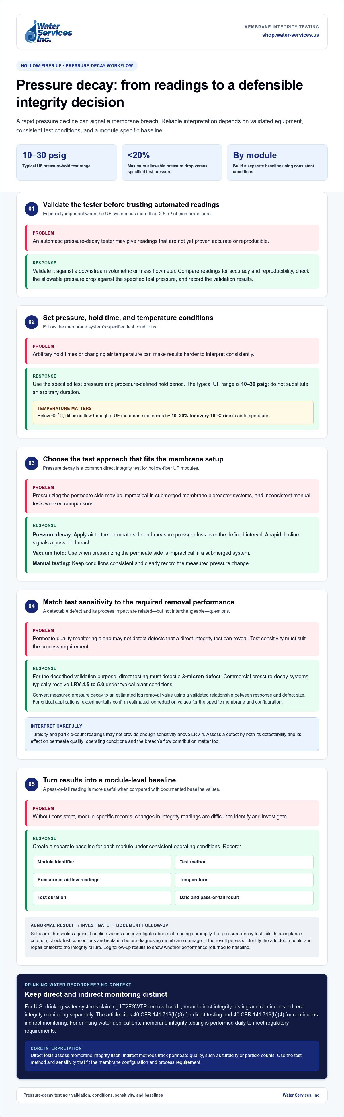
Validate the automatic tester against a downstream volumetric or mass flowmeter when the UF system has more than 2.5 m² of membrane area. Compare readings to confirm accuracy and reproducibility before relying on automated results. Check the allowable pressure drop against the specified test pressure; the maximum should be less than 20% of that pressure. Record the validation results.
-
Set Test Pressure and Hold Conditions
Set the pressure-hold test within the typical UF range of 10-30 psig, following the membrane system’s specified test conditions. Hold the pressure for the set test period; the period depends on the test procedure, so don’t substitute an arbitrary duration. Correct for temperature: below 60 °C, diffusion flow through a UF membrane increases by 10-20% for every 10 °C rise in air temperature.
-
Run Air-Based and Vacuum Hold Tests
For a pressure-decay test, apply air to the permeate side, then measure pressure loss over the defined interval. A rapid decline signals a possible membrane breach. In submerged membrane bioreactor systems, use vacuum hold testing when pressurizing the permeate side is impractical. Manual testing requires consistent conditions and a clear record of the measured pressure change.
-
Assess Test Resolution and Sensitivity
Compare the test’s sensitivity with the process’s required pathogen-removal performance. Direct testing must detect a 3-micron defect for the described validation purpose; commercially available pressure-decay systems typically resolve LRV 4.5 to 5.0 under typical plant conditions. Convert pressure decay to an estimated log removal value using a validated relationship between the measured response and defect size. For critical applications, experimentally confirm estimated log reduction values for the specific membrane and configuration.
Integrity test documentation and baseline values
For U.S. drinking-water systems claiming LT2ESWTR removal credit, record direct and continuous indirect integrity monitoring separately. Isolate and depressurize equipment before test connections, protect permeate quality from bypass, and schedule testing around filtration operations.
-
Review Integrity-Test Requirements and Principles
Identify whether the installation claims drinking-water removal credit under the Long Term 2 Enhanced Surface Water Treatment Rule (LT2ESWTR). Under 40 CFR 141.719(b)(3), direct integrity testing is addressed; 40 CFR 141.719(b)(4) addresses continuous indirect integrity monitoring. For drinking water applications, perform membrane integrity testing daily to meet regulatory requirements. In an air-water diffusion test, measure air passing through the wetted membrane; a breach changes the measured flow and can compromise water-quality performance.
-
Assess Test Sensitivity and System Size
Match test sensitivity to the removal performance the process must validate, rather than relying on permeate appearance alone. Turbidity and particle-count readings may not provide enough sensitivity above LRV 4. For systems with more than 10 m² of installed membrane area, a mass flowmeter is commonly used to measure diffusive airflow directly. As a reference example, a 10-m², 10-kDa UF system tested at 30 psig has a maximum allowable diffusion flow rate of 700 mL/min. Treat this as an example, not a universal acceptance threshold.
-
Document Baselines and Test Results
Create a separate baseline for each module using consistent operating conditions. Record the module identifier, test method, pressure or airflow readings, temperature, test duration, date, and pass-or-fail result. Set alarm thresholds against those baseline values, then investigate abnormal readings promptly. A pressure decay test that fails its acceptance criterion calls for checking test connections and isolation before diagnosing membrane damage. If the abnormal result persists, identify the affected module and repair or isolate the integrity failure. Log follow-up results to show whether performance returned to baseline.
Detectable defect size and process yield impact
Assess a defect by both its detectability and its effect on permeate quality. Even a small leak can affect removal performance and process yield, despite a large total membrane area.
-
Assess Detectable Defect Size
Compare the test’s detection threshold with the defect size that could compromise required removal performance. Pore size alone doesn’t establish the impact: operating conditions and the breach’s flow contribution also matter. In a modeled 1-m² system, a 54-µm defect accounts for approximately 0.6% of total process flux under the stated conditions. Use this example to distinguish a detected defect from its contribution to overall filtration output.
Consider system scale, too. The ASTM D6908 example compares a 10-module system with one defect to a 100-module system with 10 same-size defects. Both produce the same water quality in that example. Don’t treat a low defect count as proof that removal performance is unaffected.
-
Detect Leaks and Membrane Breaches
Use a direct integrity test to detect a breach, then narrow the location before selecting a repair procedure. A pressure-decay result can identify loss of integrity, while sonic analysis can locate leaks by detecting escaping-air sound. Test smaller membrane portions when practical; ASTM D6908 states that smaller test portions increase sensitivity to defects.
Check results against process indicators as well. Filtrate turbidity and particle-count data may not provide enough sensitivity to validate processes operating above LRV 4. Treat those readings as indirect monitoring, not a substitute for a direct test when higher removal performance must be demonstrated.
-
Repair Leaks and Assess Process Yield
After locating a leaking fiber, isolate it using a suitable repair procedure. Pin repair seals the fiber ends with suitable pins; epoxy injection into a membrane fiber is another industry repair method. Retest the affected module after repair and record the result alongside the original finding.
Estimate yield impact from the defect’s flux contribution and process duration. In the modeled 54-µm defect scenario, a five-diavolume process has an estimated yield loss of approximately 3%. Use that example to assess how defect flow can accumulate across a process, rather than equating defect size directly with lost yield.
Direct integrity testing for ultrafiltration membranes
Choose direct testing when you need a measured indication of membrane breach, not only permeate-quality trends. ASTM D6908-06(2017) is the Standard Practice for Integrity Testing of Water Filtration Membrane Systems, according to ASTM International.
-
Identify Direct Integrity Test Methods
Choose a method suited to the module configuration and the defect signal you need to measure. Pressure or vacuum decay tracks pressure change; an air-hold test measures pressure retention, while diffusive airflow measures air passing through a wetted membrane. Water displacement and marker tests are also used in membrane filtration systems. For hollow-fiber UF, pressure decay applies air to the permeate side; marker tests instead detect a selected marker passing across the membrane.
Compare each method’s measurement with the process target. Direct integrity testing must detect a 3-micron defect for the described pathogen-removal validation purpose. Commercial pressure-decay systems typically provide 4.5 to 5.0 LRV resolution under typical plant operating conditions. A test result is meaningful only when its sensitivity matches the required performance.
-
Compare Direct and Indirect Tests
Match the monitoring method to the decision you need to make. Direct tests measure membrane integrity; indirect methods assess permeate quality through measures such as turbidity or particle counts. Indirect readings may not provide enough sensitivity to validate processes operating above LRV 4, while direct-test sensitivity is tied to the method and test setup.
Compare costs based on each system’s equipment and installation requirements, rather than assuming one approach is always cheaper. Direct tests use little water and mostly compressed air, but their duration affects the timing of other UF operating modes. Indirect monitoring can run alongside filtration, while a direct test needs a defined testing period. Build that period into the operating schedule and choose a method based on detection needs, instrumentation, and production constraints.
Water Services: Goulds Water Technology Pumps
Water Services, Inc. offers Goulds Water Technology Pumps for water-treatment systems where dependable pumping equipment is part of the process design. If integrity-test findings prompt a review of the wider treatment train, consider how pumping needs relate to filtration flow and operating requirements.
Water Services, Inc. also offers Viqua UV Water Purification Systems, Hydranautics RO Membranes, and Water Treatment Antiscalants and Chemicals. These products serve different treatment stages, so choose them according to system requirements, not as substitutes for UF integrity testing. Assess pressure-decay results against membrane-specific test criteria and documented operating baselines.
Contact Water Services, Inc. to discuss equipment options for your water-treatment setup.
Turn test findings into a practical next step
Use integrity-test results to guide the next decision for your treatment process. A consistent approach to membrane integrity testing for UF systems helps connect test findings with maintenance priorities and broader system requirements. Consider how membrane performance fits alongside the equipment and treatment stages around it.
Water Services, Inc. offers Goulds Water Technology Pumps, Viqua UV Water Purification Systems, and FilmTec Reverse Osmosis Membranes for water-treatment applications. These products support distinct process needs, so match equipment choices to the role each stage must perform. A clear understanding of system requirements makes the evaluation more focused.
For support with water-treatment equipment options, contact Water Services, Inc. Keep your process goals at the center of the decision, and move forward with a sound basis for maintaining system performance.
Frequently Asked Questions
What is membrane integrity testing for ultrafiltration (UF) systems?
Membrane integrity testing for UF systems checks whether membrane modules have breaches that could affect filtration performance. Direct tests measure a physical response, such as air passage or pressure change; indirect tests track permeate indicators. For example, compare a module’s direct-test result with its own baseline, then use turbidity or particle-count trends to monitor water quality between tests.
How do you perform a pressure decay test on a UF membrane step by step?
Isolate the module and prepare the permeate side for testing. Apply air at the specified test pressure, allow conditions to stabilize, then record pressure loss over the prescribed interval. Compare the decline with the system’s acceptance criterion. If the result is abnormal, check test connections and isolation, then repeat the test before attributing the reading to a membrane breach.
How is UF membrane integrity test sensitivity or log removal value calculated?
Relate measured pressure decay or diffusive airflow to a validated calibration for the membrane and system configuration. This relationship estimates defect sensitivity or log removal value; pressure loss alone does not provide a universal conversion. For critical applications, experimentally confirm estimated log reduction values using the specific membrane and configuration. This verifies that the test response represents the required removal performance.
What are typical acceptance limits for UF membrane integrity tests?
For automated integrity tests, the maximum allowable pressure drop should be less than 20% of the specified pressure. Treat this as a criterion for automated testing, not a universal pass limit for every UF module. Acceptance also depends on whether the test can detect defects that would compromise the process’s required log removal value and whether the measured result meets the system’s specified test conditions.
What do U.S. EPA regulations require for membrane filtration integrity testing in drinking water systems?
For U.S. drinking-water installations claiming removal credit under the LT2ESWTR, 40 CFR 141.719(b)(3) addresses direct integrity testing, while 40 CFR 141.719(b)(4) addresses continuous indirect integrity monitoring. Perform membrane integrity testing daily for drinking-water applications. Keep direct-test records distinct from ongoing indirect monitoring so each result can be evaluated against its purpose and the applicable removal-credit process.
How often should UF membrane integrity testing be performed?
For drinking-water applications, perform membrane integrity testing daily to meet regulatory requirements. In wastewater membrane bioreactor applications, weekly or monthly testing is typical. Set the schedule according to the application and monitoring requirements, accounting for time direct testing takes away from other UF operating modes. Continuous indirect monitoring can provide additional permeate-quality information between direct tests.
0 comentarios