
Over-sizing a pump by just 10% often leads to a 30% increase in energy consumption and accelerated mechanical wear. You understand that selecting hardware based on "worst-case" estimates rather than precise calculations causes costly downtime and cavitation damage. Learning how to size a centrifugal pump for industrial use requires more than a simple flow estimate. It demands a rigorous analysis of system resistance and fluid properties. This guide provides the technical framework to master these calculations and ensure your equipment operates at its Best Efficiency Point (BEP).
We will detail the exact steps to align GPM and Total Dynamic Head (TDH) while maintaining critical safety margins. You'll learn why the American National Standards Institute (ANSI) recommends maintaining an NPSHa that exceeds NPSHr by at least 1.6 feet or 20% to prevent vapor bubbles from destroying your impellers. We also examine how integrating Goulds Water Technology Pumps with modern Variable Frequency Drives (VFDs) can improve energy efficiency by up to 30%. This precision approach reduces maintenance costs and secures long-term system reliability for your facility.
Key Takeaways
- Avoid the mechanical wear and excessive energy consumption associated with oversized equipment by aligning pump performance with actual system resistance.
- Master the technical methodology for how to size a centrifugal pump for industrial use through precise Flow Rate (GPM) and Total Dynamic Head (TDH) calculations.
- Account for fluid viscosity and specific gravity to ensure the system maintains a sufficient Net Positive Suction Head (NPSH) margin to prevent cavitation.
- Utilize manufacturer performance curves to identify the Best Efficiency Point (BEP) and select the optimal impeller diameter for your application.
- Specify the correct Goulds Water Technology pump models and metallurgy to ensure long-term reliability in corrosive or high-pressure industrial environments.
The Fundamentals of Industrial Centrifugal Pump Sizing
Sizing is the technical process of matching a pump's hydraulic performance to the specific requirements of an industrial system. It's not a matter of selecting the largest available motor. Instead, it involves calculating the precise intersection of the system's resistance and the pump's capability. This intersection is known as the duty point. Understanding Centrifugal Pumps and their operational limits is the first step toward achieving system stability. When you learn how to size a centrifugal pump for industrial use, you prioritize the alignment of three critical variables: Flow Rate (Q), Total Dynamic Head (TDH), and Net Positive Suction Head (NPSH).
The industrial sector often suffers from the "bigger is better" fallacy. Oversizing a pump leads to immediate operational inefficiencies. If a pump operates too far to the left of its Best Efficiency Point (BEP), internal recirculation occurs. This creates excessive vibration and heat. These forces degrade mechanical seals and bearings rapidly. Precise sizing ensures the pump handles the required volume without consuming unnecessary kilowatts or causing premature mechanical failure. It's about finding the mechanical sweet spot where the hardware performs reliably for years.
Why Precision Sizing Matters in 2026
Current industrial standards in 2026 place a heavy emphasis on energy efficiency and sustainability mandates. Procurement decisions now focus on the Total Cost of Ownership (TCO) rather than the initial purchase price. An accurately sized pump reduces energy consumption by 25% to 30% when paired with modern controls. You can find high-performance Goulds Water Technology Pumps designed to meet these rigorous hydraulic standards. Correct matching prevents the shaft deflections that lead to seal leaks; this ensures your facility maintains uptime in demanding commercial environments.
Common Industrial Sizing Mistakes to Avoid
Relying on "rules of thumb" is a frequent cause of system failure. Estimating TDH without calculating friction loss in valves and fittings leads to significant performance gaps. You must also account for future variables. For instance, pipe scaling over five years increases friction; this shifts the system curve and reduces flow. Another critical oversight involves atmospheric pressure. At high-altitude mining sites, the available NPSH decreases significantly. Failing to adjust for this reality results in cavitation, which can destroy an impeller in weeks. Mastering how to size a centrifugal pump for industrial use requires accounting for these environmental and long-term variables from the start.
Step-by-Step: Calculating Flow Rate and Total Dynamic Head (TDH)
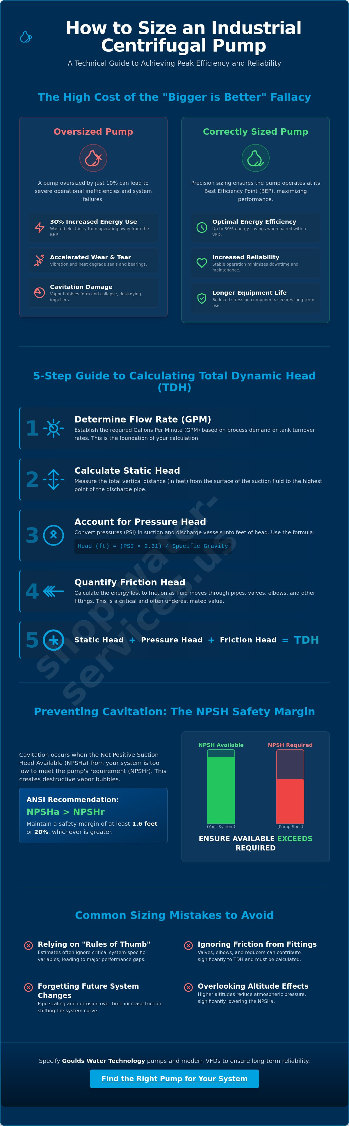
Technical accuracy in calculating Total Dynamic Head (TDH) determines the operational success of your pumping system. TDH represents the total work the pump must perform to move fluid through the system. It's the sum of elevation changes, pressure differentials, and frictional resistance. When you analyze how to size a centrifugal pump for industrial use, you must follow a structured workflow to avoid the common pitfalls of underperformance or mechanical cavitation. This process begins with five essential steps:
- Step 1: Determine Flow Rate (GPM). Establish the required volume per minute based on process demand or tank turnover rates.
- Step 2: Calculate Static Head. Measure the vertical distance from the suction fluid surface to the highest discharge point.
- Step 3: Account for Pressure Head. Convert vessel pressures (PSI) at the suction and discharge into feet of head using the formula: (PSI x 2.31) / Specific Gravity.
- Step 4: Quantify Friction Head. Calculate the energy lost as fluid interacts with pipe walls, valves, and fittings.
- Step 5: Sum the Components. Combine Static Head, Pressure Head, and Friction Head to find the TDH.
Determining Your System Flow Requirements
Your flow requirement depends entirely on the application. A containerized reverse osmosis plant requires a precise, constant GPM to maintain membrane flux, while mine dewatering applications often prioritize high-volume removal during peak influx. You should analyze historical water flow meter gpm data to establish a baseline. For municipal or military installations, always account for peak demand rather than daily averages to ensure the system doesn't fail during high-stress periods. If your process includes chemical dosing, verify that the flow remains consistent enough for Pulsafeeder metering pumps to operate within their calibrated range.
Mastering Friction Loss Calculations
Friction head is the most variable component of TDH. Engineers typically use the Hazen-Williams equation to determine these losses. The pipe material significantly impacts this calculation; for instance, PVC has a higher C-factor (smoothness) than aged carbon steel. You must also calculate the equivalent length for every elbow, tee, and valve in the line. Don't forget the pressure drop across filtration housings or heat exchangers. These individual losses add up quickly and can shift your duty point away from the pump's efficiency zone. For precise hardware selection, you can review our technical industrial pump specifications to match your calculated TDH with the right performance curve.
Analyzing Fluid Properties and NPSH Requirements
Fluid characteristics dictate the mechanical limits of your pumping hardware. When evaluating how to size a centrifugal pump for industrial use, ignoring Specific Gravity (SG) or viscosity leads to immediate motor overload or hydraulic failure. Water is the standard baseline, but industrial applications frequently involve brines, slurries, or chemical concentrates with higher densities. Specific Gravity directly impacts the Brake Horsepower (BHP) required to maintain the duty point. If your fluid is 20% denser than water, your motor must provide 20% more power to achieve the same head and flow.
Viscosity introduces another layer of complexity. Standard centrifugal pumps operate efficiently with fluids below 50 to 110 cSt. Beyond this threshold, the internal friction within the pump casing increases dramatically. This results in a sharp drop in Total Dynamic Head and a significant rise in power consumption. For high-viscosity or high-solids applications, you must specify specialized Goulds Water Technology Pumps designed with recessed impellers or hardened materials to handle the increased mechanical stress.
Specific Gravity and Viscosity Adjustments
A pump sized strictly for water will fail when tasked with moving mining wastewater or heavy chemical process fluids. You must adjust the BHP formula to account for the fluid's density: BHP = (GPM x TDH x SG) / (3960 x Pump Efficiency). Failing to include the SG multiplier results in a tripped circuit breaker or a burned-out motor. In high-solids environments, viscosity also requires a derating of the pump's performance curve. This ensures the hardware doesn't deviate from its intended hydraulic path under the weight of the medium.
Calculating Net Positive Suction Head (NPSH)
Cavitation is the primary cause of industrial impeller destruction. It occurs when the pressure at the pump suction falls below the fluid's vapor pressure, causing bubbles to form and collapse violently. To prevent this, your Net Positive Suction Head Available (NPSHa) must be significantly higher than the Net Positive Suction Head Required (NPSHr). Industry standards as of June 2026 recommend that NPSHa exceed NPSHr by at least 1.6 feet or a margin of 10% to 20%.
You can calculate NPSHa using atmospheric pressure, static suction head, and vapor pressure data. If your margin is too thin, consider these practical adjustments:
- Increase the diameter of the suction piping to reduce friction loss.
- Elevate the source tank to increase static suction head.
- Lower the fluid temperature to reduce its vapor pressure.
- Install the pump at a lower elevation relative to the fluid source.
Maintaining this safety margin is a fundamental requirement in how to size a centrifugal pump for industrial use. It protects the mechanical integrity of the pump and ensures the system operates without the vibration and noise associated with suction-side instability.
Reading Pump Performance Curves for Efficiency
After calculating TDH and NPSH, you must translate these values onto a manufacturer's performance curve. This graph illustrates the relationship between head, flow, and efficiency for a specific pump model. Understanding how to size a centrifugal pump for industrial use culminates in identifying the Best Efficiency Point (BEP). The BEP is the specific flow rate where the pump operates with the least amount of internal turbulence and vibration. Operating too far left or right of this point increases radial loads on the shaft. It also shortens the lifespan of bearings and mechanical seals.
Curves typically display multiple lines representing different impeller diameters within the same pump casing. Trimming an impeller allows you to match a specific duty point without replacing the entire motor. However, you must examine the Horsepower Curve across the entire range of operation. Ensure the motor is non-overloading even if the system pressure drops and the flow increases toward "run-out" conditions. You also need to verify the Minimum Continuous Stable Flow. Operating below this threshold causes internal heat buildup and cavitation that can damage the pump casing and internal components.
The Intersection of System Curves and Pump Curves
Plotting your system curve against the pump curve reveals the actual operating point. In many plants, the system curve is dynamic rather than static. Resistance increases as industrial water filtration systems accumulate debris or as pipe walls scale over time. This shift reduces flow and increases pressure. Selecting a pump that allows for 10% to 20% future growth ensures your system remains viable as production capacity expands. This foresight prevents the need for a total system redesign when demand increases.
Efficiency Islands and Energy Savings
Most performance curves feature "efficiency islands" that indicate the percentage of energy converted into hydraulic work. Reliable systems stay within 80% to 110% of the BEP for maximum longevity. If your process requires fluctuating flow rates, Variable Frequency Drives (VFDs) are essential. They allow the pump to follow the system curve efficiently instead of wasting energy through throttling valves. You can integrate electric power controls to monitor real-time efficiency and catch deviations before they lead to unplanned downtime. This precision approach is the final step in learning how to size a centrifugal pump for industrial use effectively. For professional-grade hardware, view our selection of Goulds Water Technology pumps to find the ideal performance curve for your application.
Procurement: Selecting Goulds Pumps for Industrial Sites
Procurement represents the final phase of learning how to size a centrifugal pump for industrial use. After you've established the duty point and verified NPSH margins, you must translate those technical requirements into specific hardware configurations. Goulds Water Technology Pumps offer a diverse range of hydraulic profiles designed for rigorous commercial environments. Selecting the correct model involves more than matching flow and head. You must also specify the metallurgy, seal type, and motor configuration to ensure the system withstands the specific chemical and physical demands of your facility.
Material selection is critical for system longevity. For mining wastewater or oil and gas applications, standard cast iron components often fail due to corrosion or abrasion. You should specify 316 stainless steel, CD4MCu duplex stainless steel, or specialized coatings for high-chloride or acidic environments. Mechanical seals are another vital consideration. High-pressure industrial systems require balanced seals or double-cartridge arrangements to prevent leaks and protect the environment. These choices directly impact the reliability of your industrial pumping equipment.
Goulds Pump Series for Specific Industrial Uses
Different industrial processes demand distinct pump architectures. End-suction pumps are the standard for general chemical transfer and water distribution. However, high-head applications like reverse osmosis systems often require multi-stage centrifugal pumps to achieve necessary membrane feed pressures. For remote site management or mining dewatering, submersible solutions offer the advantage of operating within the fluid source, eliminating suction lift issues. Large-scale water intake from wells or reservoirs typically utilizes vertical turbine pumps, which provide high efficiency and a small footprint for high-volume demand.
Final Checklist Before Ordering
Before finalizing your procurement, conduct a thorough technical review of the motor and safety specifications. Small errors in motor data can lead to significant installation delays. Verify the following data points:
- Electrical Specifications: Confirm the voltage, phase, and frequency (Hz) align with your facility's power grid.
- Enclosure Type: Specify TEFC (Totally Enclosed Fan Cooled) or explosion-proof motors for hazardous industrial areas.
- Safety Protocols: Ensure your team has the necessary PPE and rigging equipment for a safe installation.
- Ancillary Components: Verify that your Ashcroft pressure gauges and Signet flow sensors are compatible with the pump's discharge and suction ports.
Engineering a reliable system requires precision at every step. If you've completed your calculations for how to size a centrifugal pump for industrial use but require a secondary review, contact our technical team. We provide a secondary engineering verification of your sizing data to ensure your Goulds pump selection perfectly matches your system demand. This final check secures your investment and guarantees the operational integrity of your industrial plant.
Securing Long-Term Pumping Reliability
Precision engineering prevents the operational instability that often plagues oversized systems. You've seen that aligning your system curve with the Best Efficiency Point and maintaining rigorous NPSH safety margins protects infrastructure from cavitation and premature seal failure. Mastering how to size a centrifugal pump for industrial use ensures your facility avoids the mechanical failures and energy waste associated with hydraulic mismatching. This technical discipline is the foundation of a stable, cost-effective industrial plant.
Water Services, Inc. is an Authorized Goulds Water Technology Distributor. We've provided global engineering support since 1994 and maintain specialized expertise in mining and oil & gas water systems. Our technical team is ready to verify your hydraulic calculations to ensure your hardware selection meets the specific rigors of your environment. We focus on technical integrity so your equipment performs as specified under the most demanding conditions.
Browse our full inventory of Goulds Water Technology Pumps to select a high-performance solution for your next project. It's time to optimize your system for decades of reliable service.
Frequently Asked Questions
What is the most important factor when sizing a centrifugal pump?
The primary factor is the precise alignment of the duty point with the system curve. You must ensure the pump operates near its Best Efficiency Point to minimize radial loads. This alignment is the core objective of how to size a centrifugal pump for industrial use. Accurate sizing prevents the mechanical vibration and thermal stress that lead to premature bearing failure in demanding commercial environments.
How do I calculate Total Dynamic Head (TDH) for my system?
Calculate TDH by summing the Static Head, Pressure Head, and Friction Head. Use the vertical elevation change for static head and convert vessel PSI to feet for pressure head. Friction head requires quantifying the resistance from every pipe, valve, and fitting using the Hazen-Williams equation. This total value defines the work the pump must perform to move fluid through your specific industrial piping network.
What happens if I select a pump that is too large for my application?
Selecting an oversized pump leads to significant energy waste and accelerated mechanical wear. When a pump operates too far to the left of the BEP, it causes internal recirculation and excessive shaft deflection. These forces destroy mechanical seals and bearings. You will face higher operational costs and more frequent unplanned downtime compared to a system using a correctly sized Goulds Water Technology pump.
How does fluid viscosity affect centrifugal pump performance?
High fluid viscosity increases internal friction and reduces the pump's hydraulic efficiency. Standard centrifugal designs typically handle fluids below 110 cSt before performance drops sharply. For thicker mediums, you must derate the performance curve and increase motor horsepower to compensate for the added drag. This adjustment is a critical step in how to size a centrifugal pump for industrial use when handling chemical slurries.
What is the difference between NPSHa and NPSHr?
NPSHa is the pressure available at the pump suction, while NPSHr is the pressure required by the pump to prevent cavitation. Your system's NPSHa must always be higher than the manufacturer's NPSHr. Industry standards recommend a safety margin of at least 1.6 feet or 10 to 20 percent. This buffer ensures that vapor bubbles don't form and collapse against the impeller during standard pressure fluctuations.
How do I find the Best Efficiency Point (BEP) on a pump curve?
Locate the BEP by identifying the highest point on the efficiency curve provided in the manufacturer's technical catalog. Most industrial curves plot efficiency as a percentage against flow rate. You should aim for an operating point within 80% to 110% of this peak value. Staying within this efficiency island maximizes the lifespan of your mechanical components and reduces the total cost of ownership for the system.
Can a centrifugal pump handle solids in industrial wastewater?
Yes, but you must select an impeller design specifically engineered for solids handling. Standard closed impellers will clog or erode rapidly in wastewater applications. Goulds Water Technology offers pumps with open or recessed impellers that allow solids to pass without contacting the primary hydraulic surfaces. Verify the maximum spherical solid size against the pump specifications before installation to ensure reliable operation in mining or municipal environments.
Should I use a VFD with my industrially sized pump?
You should use a Variable Frequency Drive (VFD) if your process flow requirements fluctuate. A VFD allows the pump to follow the system curve by adjusting motor speed instead of using restrictive throttling valves. This integration can improve energy efficiency by up to 30% and reduce mechanical stress during startup. It's a standard recommendation for modern industrial pumping systems seeking to optimize performance and reduce utility expenses.
0 comentarios